In this blog you will learn,What is shift register and how to use it with Arduino?
-The very first thing, why do you need a shift register ??- you need it because you want to control many devices just by one output pin of arduino ,In my case it is LED's.
- you have 100 of leds to control but you don't have that much pins then you need to call a superhero in your case the superhero is Shift Register.
- If you have 8 led's then you can easily use the arduino pin's, But you don't want to use it because you don't want 8 wire's come through your arduino.
Let's see what is shift register?
Basically there are two types of shift register one which takes serial data in from the microcontroller and gives parallel data out, and another type is the inverse of first one, means it is parallel in and serial out type.
The shift register i'm using in my example is Serial-In Parallel-Out type (74HC595). The datasheet refers to the 74HC595 as an "8-bit serial-in, serial or parallel-out shift register with output latches; 3-state." In other words, you can use it to control 8 outputs at a time while only taking up a few pins on your microcontroller. You can link multiple registers together to extend your output even more.
Here is a table explaining the pin-outs adapted from the Phillip's datasheet.
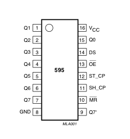 | PINS 1-7, 15 | Q0 " Q7 | Output Pins |
| PIN 8 | GND | Ground, Vss | |
| PIN 9 | Q7" | Serial Out | |
| PIN 10 | MR | Master Reclear, active low | |
| PIN 11 | SH_CP | Shift register clock pin | |
| PIN 12 | ST_CP | Storage register clock pin (latch pin) | |
| PIN 13 | OE | Output enable, active low | |
| PIN 14 | DS | Serial data input | |
| PIN 16 | Vcc | Positive supply voltage |
To understand how shift register work let's take an example-
In this example 8 led's are connected with shift register as you can see below.

Now let's suppose if you want to glow 1st,5th and 8th led's.
then you have to make 1st,5th and 8th output pin of the shift register high.
For this you have to send bits serially to the the input pin of the shift register.
so you will send "10001001" these bits to the input pin of the shift register.
Now let's start with the most signigicant bit, make the data pin of the arduino high or low according to your data bit, if the bit is one you will make the arduino data pin high, if it is low then you will make arduino data pin low.
In our case it is one so we make the arduino data pin high, And then make clock pin high to store the data_pin state in to the shift register, So at this moment your Q7 pin of the shift register is high and then make the clock pin low.
Now we will make arduino data pin according to our second data bit, In our case it is 0 so we make our data pin low, and then make the clock pin high, now the bit at the Q7 will shift to the Q6 and the new bit is stores in Q7, means the logic state of the Q7 is now LOW and the logic state of the Q6 is HIGH.
After shifting all the data bits in the shift register, the output pins of the shift register will become like this-
Q0 - 1 (HIGH)
Q1 - 0 (LOW)
Q2 - 0 (LOW)
Q3 - 0 (LOW)
Q4 - 1 (HIGH)
Q5 - 0 (LOW)
Q6 - 0 (LOW)
Q7 - 1 (HIGH)
Now all the pins of the shift register are logically set, but they are not enable yet, To make them enable make the latch pin high, So remember initially we make the latch pin low until the transition of all the bits are not completed.
After the completion of transition we make the latch pin high. So all the output pins of shift register will generate output according to the bit store in it, if the bit store in it is 0 then no current will emit from the pin and if the bit store in it is 1 then the current will flow from it.
After enabling the latch pin the 1st,5th and 8th output pin of the shiftregister will emit +ve voltage and the the 1st,5th and 8th led's will glow and you will clap.
After understanding the basics make the connection like the figure above
For the prototyping you will need following things.
1- Shiftregister 74HC595.
2- Arduino.
3- some 330 ohm resistor & 0.1 uf Capacitor
4- Breadboard.
5- some jumper wires.
After making the connection you have to copy this code and paste it to your Arduino IDE to see the demonstration of shift register.
As you can see in the main loop they are calling shiftOut function two times, Because they are using two shift registers.
If you are using one register then you can remove the second shiftout function call.
void loop() {
Or you can connect two shift registers, like the figure below and use the same code given in the link.

//ground latchPin and hold low for as long as you are transmitting
digitalWrite(latchPin, 0);
//count up on GREEN LEDs
shiftOut(dataPin, clockPin,data1);
//count down on RED LEDs
shiftOut(dataPin, clockPin,data2);
//return the latch pin high to signal chip that it
//no longer needs to listen for information
digitalWrite(latchPin, 1);
}
//end of the code//
Hey guys, thanks for reading my blog.
Please take a look at it - mYoutube
void loop() {
  //count up routine
  for (int j = 0; j < 256; j++) {
    //ground latchPin and hold low for as long as you are transmitting
    digitalWrite(latchPin, 0);
    //count up on GREEN LEDs
    shiftOut(dataPin, clockPin, j);
    //count down on RED LEDs
    shiftOut(dataPin, clockPin, 255-j);
    //return the latch pin high to signal chip that it
    //no longer needs to listen for information
    digitalWrite(latchPin, 1);
    delay(1000);
  }
}
To glow the 1st,5th and 8th led change the main loop code with the code given below.
void loop() {digitalWrite(latchPin, 0); shiftOut(dataPin, clockPin,0x89);//1000 1001 (Binary) = 0x8 9 (Hexadecimal) //1000 1001 (Binary) = 137 (Decimal)digitalWrite(latchPin, 1); delay(1000); } }
Or you can connect two shift registers, like the figure below and use the same code given in the link.
I write a separate function called ledWrite() to make the code easier to use. So I Modifiy the code that was written by "Carlyn Maw and Tom Igoe ".
The modified code is given below.
//Pin connected to ST_CP of 74HC595
int latchPin = 8;
//Pin connected to SH_CP of 74HC595
int clockPin = 12;
////Pin connected to DS of 74HC595
int dataPin = 11;

void setup() {
  //Start Serial for debuging purposes
  Serial.begin(9600);
  //set pins to output because they are addressed in the main loop
  pinMode(latchPin, OUTPUT);
}
void loop() {

// now you just have to call the ledWrite function by sending the data as argument
ledWrite(1,165);
delay(1000);
ledWrite(55,80);
delay(1000);

  }
}
void shiftOut(int myDataPin, int myClockPin, byte myDataOut) {
  // This shifts 8 bits out MSB first,
  //on the rising edge of the clock,
  //clock idles low
  //internal function setup
  int i=0;
  int pinState;
  pinMode(myClockPin, OUTPUT);
  pinMode(myDataPin, OUTPUT);
   //clear everything out just in case to
   //prepare shift register for bit shifting
  digitalWrite(myDataPin, 0);
  digitalWrite(myClockPin, 0);
  //for each bit in the byte myDataOut�
  //NOTICE THAT WE ARE COUNTING DOWN in our for loop
  //This means that 000001 or "1" will go through such
  //that it will be pin Q0 that lights.
  for (i=7; i>=0; i--)  {
    digitalWrite(myClockPin, 0);
    //if the value passed to myDataOut and a bitmask result
    // true then... so if we are at i=6 and our value is
    // %11010100 it would the code compares it to %01000000
    // and proceeds to set pinState to 1.
    if ( myDataOut & (1<<i) ) {
      pinState= 1;
    }
    else {
      pinState= 0;
    }
    //Sets the pin to HIGH or LOW depending on pinState
    digitalWrite(myDataPin, pinState);
    //register shifts bits on upstroke of clock pin
    digitalWrite(myClockPin, 1);
    //zero the data pin after shift to prevent bleed through
    digitalWrite(myDataPin, 0);
  }
  //stop shifting
  digitalWrite(myClockPin, 0);
}
void ledWrite(int data1,int data2)
{//ground latchPin and hold low for as long as you are transmitting
digitalWrite(latchPin, 0);
//count up on GREEN LEDs
shiftOut(dataPin, clockPin,data1);
//count down on RED LEDs
shiftOut(dataPin, clockPin,data2);
//return the latch pin high to signal chip that it
//no longer needs to listen for information
digitalWrite(latchPin, 1);
}
//end of the code//
Hey guys, thanks for reading my blog.
I've made a chrome extension mYoutube for YouTube™. It is designed for a more comfortable watching experience.
✔ Instant control over volume by scrolling mouse wheel on the video.

✔ You can permanently disable video Annotations.

✔ Read Comments, see Related-Videos and Info without leaving video from sight.

✔ Auto turn off lights, when mouse stays more than 2 seconds on the video player.
Please take a look at it - mYoutube

hiii... can you please tell me about the capacitor you used here. is it a 0.1f capacitor or 0.1uf capacitor.?
ReplyDeleteCapacitor used here is 0.1 uf.
DeleteHey when i verify this code i have an error:
ReplyDeleteexit status 1
'ledWrite' was not declared in this scope
Your wiring diagram showing the two shift registers has an error: left register pin 9 should connect to right register pin 14.
ReplyDeletePlease clarify the shift registers wiring diagram,11,12,14th pin are connected with the same of second one?or else kindly clarify,,,
DeleteCielo Columbia Titanium Pants - TITanium-arts.com
ReplyDeleteCielo Columbia Brand Cotton Cotton Cotton Cotton Cotton Cotton Cotton Cotton Cotton Cotton Cotton Cotton Cotton micro touch titanium trim Cotton titanium camping cookware Cotton Cotton Cotton Cotton titanium mesh Cotton Cotton Cotton Cotton Cotton Cotton Cotton Cotton Cotton Cotton Cotton Cotton smith titanium Cotton Cotton Cotton Cotton Cotton Cotton Cotton Cotton Cotton Cotton Cotton titanium ranger Cotton
Great and I have a keen give: Renovation House Company house renovation training
ReplyDelete